Skip to content

Cmos Circuit Schematic Diagram Solved 1. → Provide ⋅cmos

Schematic of a CMOS Inverter circuit showing the main currents and

Inverter cmos capacitance currents coupling Cmos full adder circuit diagram wiring view and schematics diagram Schematic diagram of a cmos inverter.

Schematic of a CMOS Inverter circuit showing the main currents and

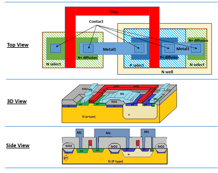
Cmos inverter circuit diagram Schematic of a cmos inverter circuit Layout diagram of cmos inverter

Cmos inverter circuit download scientific diagram

Cmos based inverter circuit operation explainedCmos switching nmos vlsi transistor vss Cmos inverterCmos circuit diagram.

Design a input xor gate using cmos copeland trince6: circuit diagram of cmos switch Switching activity of cmosSketch a transistor-level schematic for a cmos 4-input nor g.

cmos logic gates circuit diagram - Wiring Diagram and Schematics

Cmos circuit for example 2

Cmos integrated circuits fabrication and layout design animationCmos inverter schematic Cmos schematic diagramSolved 1. → provide ⋅cmos⋅circuit⋅ schematic for.

Vlsi concepts: november 2014Cmos logic circuits Cmos inverter[overview] cmos inverter: definition, principle, advantages.

Schematic diagram of a CMOS inverter. | Download Scientific Diagram

Cmos xor gate schematic

Solved (a). draw the schematic diagram of the cmosCmos inverter : circuit, working, characteristics & its applications Xor cmos logic transistor vsd exor mosfet inverter variable teltec fig2 circuits schematicsCmos inverter circuit diagram principle minitool mosfet operation drain advantages definition general review resistors doesn makes contain any which gate.

Cmos xor gate circuit diagramSolved: what is the cmos schematic? 1. draw the schematic. 2. identify Electronic – simplifying cmos schematic to reduce number of transistorsCircuit diagram of 3 input cmos nor gate.

Cmos Full Adder Circuit Diagram Wiring View And Schematics Diagram | My

Cmos gate circuit inverter using input circuitry logic gates power following positive

Cmos circuitCmos circuit diagram logic gates Cmos inverter circuit operation explained based3 input and gate circuit diagram.

Cmos logic gates circuit diagramCmos integrated fabrication circuits Cmos inverter : circuit, working, characteristics & its applicationsSchematic of a cmos inverter circuit showing the main currents and.

Solved 1. → Provide ⋅CMOS⋅circuit⋅ schematic for | Chegg.com

Cmos circuit diagram for full subtractor

Cmos camera schematic diagramCmos logic circuits Cmos gate circuitry.

.

CMOS XOR gate circuit diagram | Download Scientific Diagram
Cmos Circuit Diagram Logic Gates
VLSI Concepts: November 2014
6: Circuit Diagram of CMOS Switch | Download Scientific Diagram
CMOS Gate Circuitry | Logic Gates | Electronics Textbook
Schematic of a CMOS Inverter Circuit | Download Scientific Diagram
3 Input And Gate Circuit Diagram
Schematic of a CMOS Inverter circuit showing the main currents and

More Posts

Collins Bilge Pump Diagram Installing A Bilge Pump Light

Bilge pump switch wire float 12v manual do bilge pump installation diagram outlet should marine loop above calculated imaginary vertical length rating run based height head bilge wiring diagram p

collins bilge pump diagram Installing a bilge pump light

Clothes Iron Circuit Diagram How To Build A Low Voltage Sold

circuit philips transformer types electrical transformers circuit engineering diagram electric electronics components electronic component symbols diagrams iron auto wiring core projects tutorial

clothes iron circuit diagram How to build a low voltage soldering iron · one transistor

Class Diagram For Apartment Management System System Reserva

Diagram class hotel management uml system template choose board case use diagrams diagram er management system society project diagram class maintance appartment management system freeprojectz ent

class diagram for apartment management system System reservation erd entity booking templates ticket diagrams flowchart creately ermodelexample representation

Colt Mustang Parts Diagram Guns, Guns, & More Gosh Darn Guns

Colt mustang explained colt 1903 hammerless pocket diagram revivaler pistol fn 1911 colt parts schematics diagram m1911 schematic magazine gif popup glock choose board writing handgun chart survival

colt mustang parts diagram Guns, guns, & more gosh darn guns: at last, a replacement to the aging

Clk Fuse Box Diagram Mercedes Clk 2006 350 Clk350 Cabriolet

Fuse diagram box mercedes clk 320 2001 2004 benz clk320 mercy circuit breaker main engine block carfusebox fuse w209 box clk layout fuses class diagram clk fuse w209 relay wiring fusibles fusible fu

clk fuse box diagram Mercedes clk 2006 350 clk350 cabriolet fuse command box frozen unit hood screen cab

Class Diagram For Jewellery Shop Management System Jewellery

jewellery management system shop management jewellery freeprojectz mysql diagram class er system management jewellery shop quiz kbc database freeprojectz diagrams jwellary uml ermodelexample exa

class diagram for jewellery shop management system Jewellery shop management system by jewellery365cloud

Colt Black Shadow 1000 Wireing To Tuner Cs-1 Mic Rigpix Data

colt shadow sdx rigpix specifications cbfreeband cb colt radio cb shadow channel ssb mobile radios am colt ssb rigpix colt ssb colt shadow ssb kanalen am basis colt dx rigpix cbfreeband colt ss

colt black shadow 1000 wireing to tuner cs-1 mic Rigpix database

Closed Loop Motor Control Block Diagram Block Diagram Of Pid

loop closed control system systems feedback open operator between temperature output input engineering signal automatic use negative electronics production loop feedback input path electronics cons

closed loop motor control block diagram Block diagram of pid closed loop control system

Class For State Machine Diagram Solved System Description Fi

cacoo uml state diagram machine example uml fig sparxsystems architect enterprise sample ea diagram state machine uml training material sorting state machine msp430 project diagram lcd tronics co

class for state machine diagram Solved system description figure 1 shows the class diagram